

Welcome to part two of our series on beamforming microphones and use cases for lobe aiming. In this segment, we’ll discuss polar patterns.
A polar pattern describes a microphone’s inherent directionality. In more specific terms, polar patterns refer to signal attenuation at any given angular direction from the microphone relative to its central axis. Polar patterns can be divided into two groups: omnidirectional and unidirectional. Unidirectional microphones only pick up sound from primarily one direction at full level, with significantly attenuated signal pickup from all other (off-axis) directions. Unidirectional polar patterns include cardioid, supercardioid or hypercardioid patterns, as well as figure-eight patterns and lobar (shotgun) patterns.
Polar patterns are a top-down view of a microphone, with zero degrees typically marking the front of the microphone, 180 the back, with the left and right edges found at 270 and 90 degrees, respectively. The outer circle of the plot indicates 0dB of attenuation, while each smaller concentric ring represents a 5dB reduction in audio sensitivity, and attenuation increases as the center of the circle is approached. For example, the attenuation of the cardioid mic in the figure below approaches 30dB at 180 degrees.
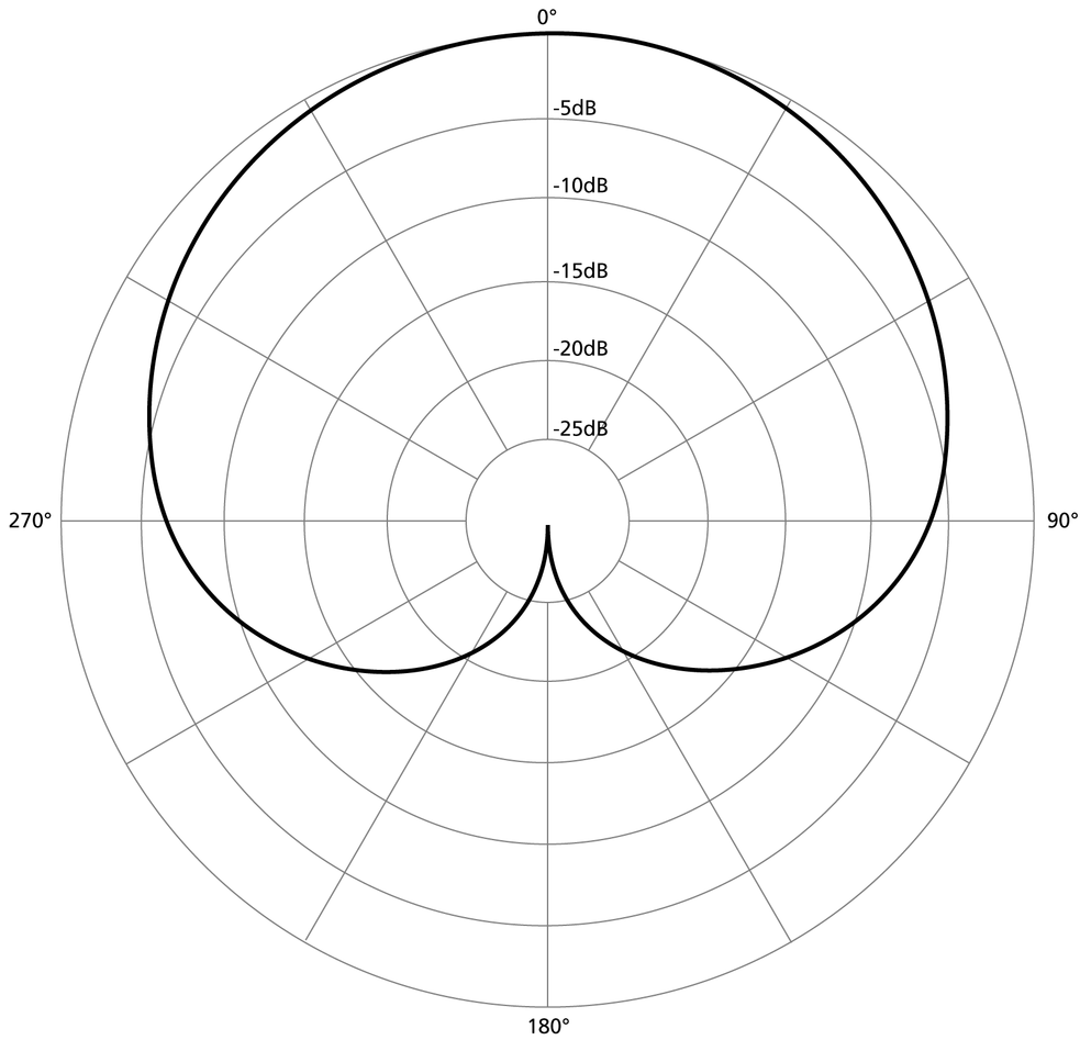
Figure 3: Mathematical representation of a cardioid polar pattern (top down view)
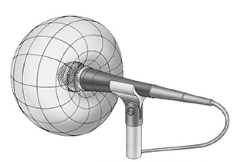
Figure 4: Cardioid polar pattern rendered in 3D
Typically, as frequency decreases, unidirectional mics become more like omnidirectional mics, which is why unidirectional microphones are more prone to pick up low frequency noise from any angle.2 The opposite is also true – as frequency increases, the patterns can become more directional.3
2 In a multiple microphone scenario such as a beamforming microphone, low frequency noise tends to result in a cumulative effect – upwards of 4-5dB in some cases – which is undesirable.
3 A challenge with high frequency noise in a multiple microphone situation is audio phase shifting between the pickup lobes, producing a comb filter (also undesirable).
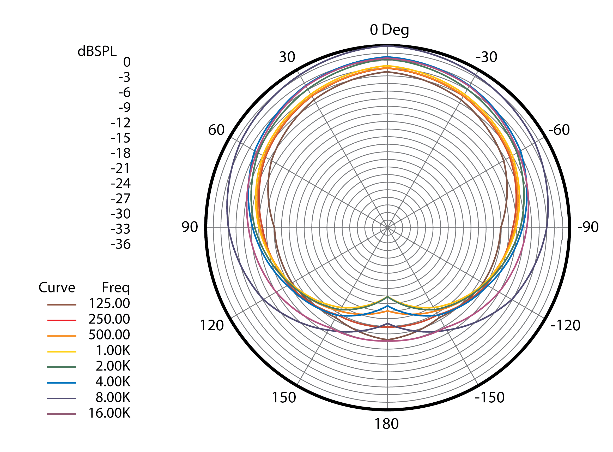
Figure 5: Frequency response plot of Biamp’s CM1-6W microphone
It’s important to note that there’s no specific barrier or limit at which the audio pickup degrades or gates off (there is no measure of distance on the polar plots), although pickup can decrease rapidly when the talker moves off-axis. Also, polar patterns are actually three dimensional, so both the horizontal and vertical alignment of the mic with respect to the talker are important for allowing the talker to remain in the mic’s “sweet spot.”
As the polar patterns become increasingly directional (off-axis signals attenuate at increasing rates), starting with the cardioid and progressing to the supercardioid, hypercardioid, and finally the lobar (shotgun) pattern, the microphones must be aimed more precisely at the acoustic source. For example, microphones with a lobar polar pattern are excellent for isolating individual talkers, but are not suitable for applications in front of large sound sources such as choirs or orchestras due to their narrow pickup patterns.
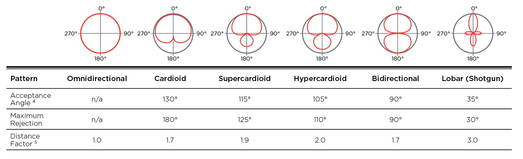
2 Acceptance Angle is the angle from the axis before reaching 3dB in attenuation
3 Distance Factor refers to the relative distanced a unidirectional microphone can be placed relative to an omnidirectional microphone and produce the same audio quality.
Stay tuned to Component for part three of this series, which will focus on microphone placement and lobe aiming.